
TM 5-2420-230-24-1
(17) Remove 6 bolts, 12 washers, 6 self-locking nuts and fan blade. Discard self-locking nuts.
(18) Disconnect three hydraulic hoses to fan hydraulic motor.
(19) Remove 8 bolts, 16 washers, and 8 self-locking nuts securing fan motor support to chassis. Discard self-locking
nuts.
(20) Remove fan hydraulic motor and fan motor support from engine bay.
(21) Remove drive belt (Para 4-6).
(22) Remove four self-locking nuts, eight washers, four bolts, and A/C compressor. Secure A/C compressor on fender
mount with cable ties. Discard self-locking nuts.
(23) Loosen clamp, remove A/C receiver drier, and secure with cable ties.
(24) Unscrew transmission filler neck and remove it.
(25) Deleted.
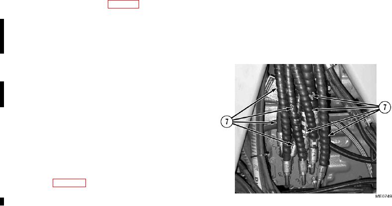
(26) Remove eight lines (7) from modulator valve on
transmission.
NOTE
Remove remote shift valve and hoses
as one assembly.
(27) Remove remote shift valve and bracket
(28) Deleted.
Change 1
4-10