
TM 5-2420-230-24-1
(34) Jack vehicle on one rear side, install jack stand (Para 2-21), and cage brake chamber (Para 8-8).
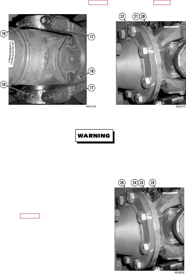
(35) Remove four bolts (17) and two retaining straps (18) securing front drive shaft (19) to differential yoke and
remove front drive shaft (19).
Drive shafts are heavy. Ensure no personnel are under a drive shaft when it is removed. Failure to
comply could result in serious injury or death to personnel.
(36) Scribe aligning mark and remove eight self-locking nuts (20), washers (21), and bolts (22) securing rear end of
front drive shaft (19). Discard self-locking nuts.
(37) Scribe aligning mark and remove eight
self-locking nuts (23), washers (24), and
bolts (25) from front end of rear drive
shaft (26). Set rear drive shaft aside. Discard
self-locking nuts.
(38) Jack vehicle, remove jack stands, and lower
vehicle (Para 2-21).
Change 1
4-12