
TM 5-2420-230-24-1
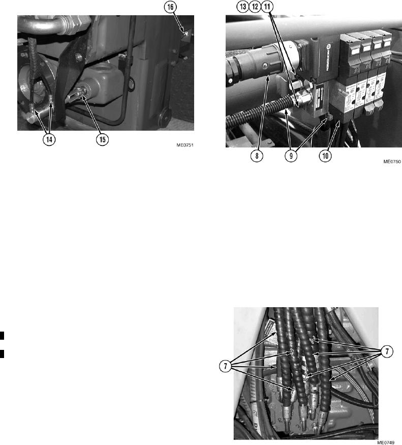
(37) Install 2WD/4WD transmission control cylinder (16) located adjacent to front drive shaft flange on front of
transmission.
(38) Install two HIGH/LOW range transmission air lines (14) to control cylinder (15) located adjacent to rear drive
shaft flange on transmission.
(39) Install pneumatic valve assembly (10) with four washers (13), screws (12), and new self-locking nuts (11).
(40) Install connector (8) and nine air lines (9) on pneumatic valve assembly (10).
(41) Position transmission hydraulic manifold and hoses on vehicle and route transmission manifold lines through
chassis.
(42) Install four bolts securing transmission hydraulic manifold to transmission.
(43) Connect five electrical connections at transmission hydraulic manifold.
(44) Remove cloth from impeller side of
turbocharger.
(45) Install air inlet duct and clamps at
turbocharger inlet and air intake pipe.
Tighten clamps.
(46) Install eight lines (7) on remote shift on
transmission.
(47) Install transmission filler neck by screwing
into place.
(48) Position fan hydraulic motor and fan motor
support in engine bay.
(49) Connect three hydraulic hoses to fan
hydraulic motor.
(50) Install fan motor support to chassis with 8 bolts, 16 washers, and 8 new self-locking nuts. Tighten bolts.
(51) Install fan blade with 6 bolts, 12 washers, and 6 new self-locking nuts. Tighten nuts to 11 lbf/ft (15 Nm).
Change 1
4-20