
TM 5-2420-230-24-1
(16) Remove cloth from turbine side of turbocharger.
(17) Install exhaust pipe at turbocharger.
(19) Remove cable ties securing A/C compressor and A/C receiver-drier.
(19.1)Install A/C receiver-drier and tighten clamp.
(19.2)Install A/C compressor with four bolts, eight washers, and four new self-locking nuts.
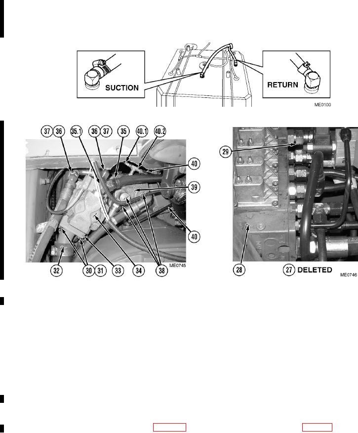
(20) Connect fuel supply and return lines on top of fuel tank and tighten clamps.
(21) Install two torque converter lockup tubes (40).
(22) Install T-fitting (40.2) and capillary tube (40.1) on transmission charge pump (39).
(23) Install three hydraulic fittings (38) on rear of transmission charge pump (39).
(24) Install hydraulic fittings (37) and hoses (36) on hydraulic pump (34).
(25) Install fitting (35.1) and hydraulic fan motor supply tube (35).
(26) Install new O-ring (33) and hydraulic supply line (32) on hydraulic pump (34) with four new lockwashers (31) and
bolts (30).
(27) Install hydraulic return line (29) located on FEL valve block (28).
(28) Deleted.
(29) Remove cloth and install hose connecting air cooler to turbocharger.
(30) Jack vehicle and place jack stands (Para 2-21) at position with brake chamber caged (Para 8-8).
Change 1
4-18