
TM 5-2420-230-24-1
5-10. STEERING WHEEL REPLACEMENT.
This Task Covers:
a. Removal
b. Installation
c. Follow-On Maintenance
INITIAL SETUP
Test Equipment
Equipment Conditions
None
TM or Para
Condition Description
Vehicle positioned on level
ground.
Tools and Special Tools
Tool kit, general mechanics, Item 38, Appendix B
Parking brake applied.
Engine shut OFF.
Electrical master switch OFF.
Materials/Parts
None
"Do Not Operate" tag attached
to ignition switch.
Personnel Required
Drawings Required
MOS 62B, Construction Equipment Repairer
TM 5-2420-230-24P Figure 108
References
Estimated Time to Complete
None
Refer to MAC in Appendix B
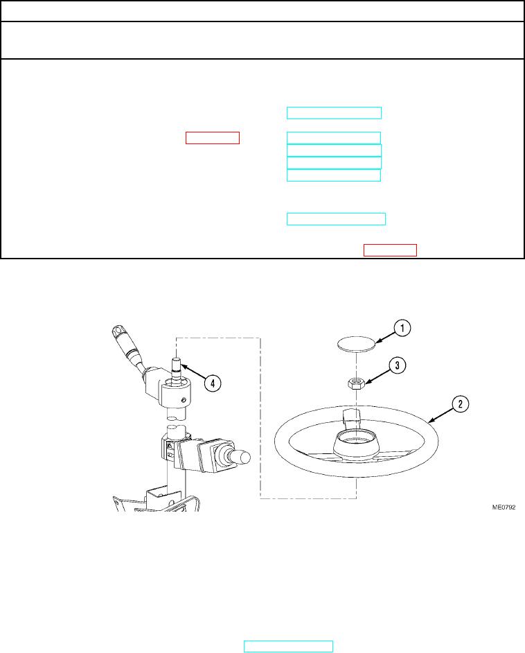
a. Removal.
NOTE
Prior to removal of the steering wheel, ensure wheels are pointing in the straight-ahead position.
(1)
Remove steering wheel cap (1) from steering wheel (2).
(2)
Remove nut (3) and steering wheel (2) from steering column shaft (4).
b. Installation.
(1)
Install steering wheel (2) and nut (3) on steering column shaft (4).
(2)
Install steering wheel cap (1) on steering wheel (2).
c. Follow-On Maintenance.
Remove "Do Not Operate" tag from ignition switch (TM 5-2420-230-10).
END OF TASK