
TM 5-2420-230-24-1
5-12. PANHARD ROD REPLACEMENT.
This Task Covers:
a. Front Panhard Rod Removal
b. Rear Panhard Rod Removal
c. Rear Panhard Rod Installation
d. Front Panhard Rod Installation
e. Adjustment
f. Follow-On Maintenance
INITIAL SETUP
Test Equipment
Equipment Conditions
None
TM or Para
Condition Description
Vehicle positioned on level
ground.
Tools and Special Tools
Tool kit, common no. 2, Item 36, Appendix B
Parking brake applied.
Tool kit, general mechanics, Item 38, Appendix B
Engine shut OFF.
Electrical master switch OFF.
"Do Not Operate" tag attached
Materials/Parts
Nut, self-locking, Item 123, Appendix D (4 per
to ignition switch.
panhard rod)
Drawings Required
TM 5-2420-230-24P Figure 120
Personnel Required
MOS 62B, Construction Equipment Repairer
Estimated Time to Complete Task
Refer to MAC in Appendix B
References
None
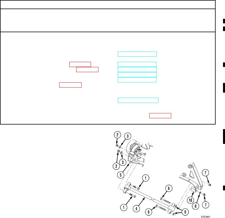
a. Front Panhard Rod Removal.
(1)
Remove two bolts (1), self-locking nuts (2),
washers (3), and front panhard rod (4) from
front axle (5). Discard self-locking nuts.
NOTE
There is no washer on the inside bolt to
connect the front panhard rod to the frame.
(2)
Remove two bolts (6), self-locking nuts (7),
washer (8), shims (9), and front panhard
rod (4) from frame (10). Discard self-locking
nuts.
Change 1