
TM 5-2420-230-24-1
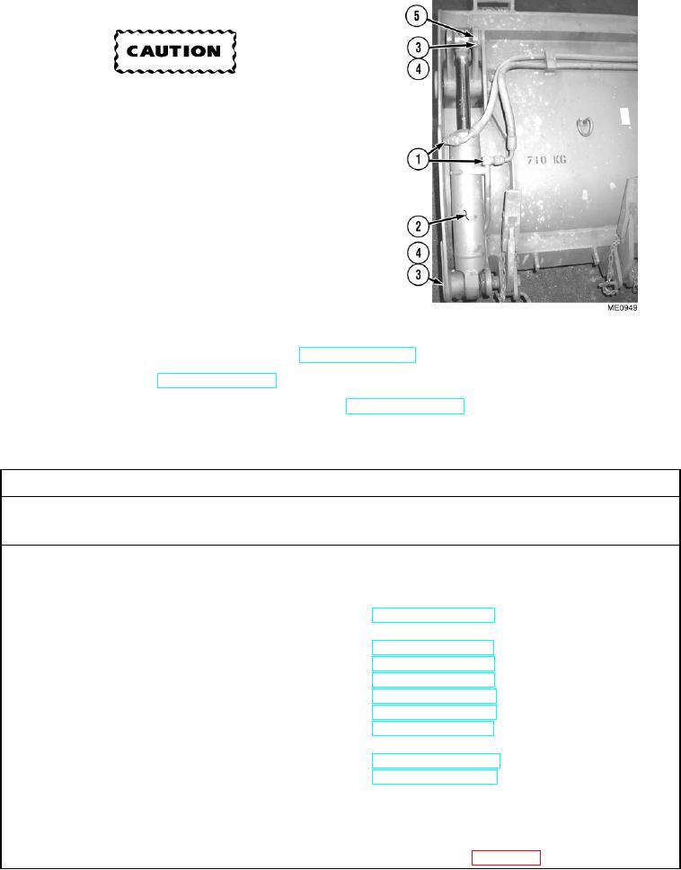
d. Installation.
Ensure pins are lubricated before installing.
Failure to comply could result in damage to
equipment.
NOTE
Ensure all hoses and tubes are reconnected to
positions noted prior to removal.
Install cable ties as necessary.
(1)
Install 4-in-1 bucket cylinder (2) with two pivot
pins (5), bolts (4), and new self-locking nuts (3).
(2)
Connect two hydraulic hoses (1) to 4-in-1
bucket cylinder (2).
e. Follow-On Maintenance.
(1)
Start engine and functionally test cylinders (TM 5-2420-230-10).
(2)
Shut OFF engine (TM 5-2420-230-10).
(3)
Remove "Do Not Operate" tag from ignition switch (TM 5-2420-230-10).
END OF TASK
10-26. HYDRAULIC CALIBRATION PROCEDURE.
This Task Covers:
a. Calibration
b. Functional Test
c. Follow-On Maintenance
INITIAL SETUP
Test Equipment
Equipment Conditions
None
TM or Para
Condition Description
Vehicle positioned on level
ground.
Tools and Special Tools
None
Parking brake applied.
Engine shut OFF.
Electrical master switch OFF.
Materials/Parts
None
Travel stops stowed.
Bucket locking clevis removed.
Headlights placed in travel
Personnel Required
MOS 62B, Construction Equipment Repairer
mode.
LOADER mode selected.
BACKHOE A mode selected.
References
FO-4, Hydraulic schematic
Drawings Required
None
Estimated Time to Complete
Refer to MAC in Appendix B
Change 1