
TM 5-2420-230-24-1
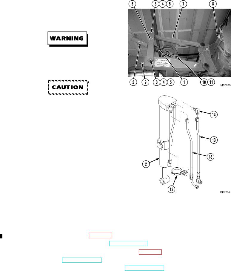
c. Assembly.
(1)
Install two elbows (14) on tilt cylinder (2).
(2)
Connect two hoses (13) to tilt cylinder (2).
(3)
Install clamp (12) on tilt cylinder (2).
d. Installation.
Use care when removing or installing snap
and retaining rings. Snap and retaining rings
are under spring tension and can act as
projectiles when released and could cause
severe eye injury.
Ensure pins are lubricated before installing.
Failure to comply could result in damage to
equipment.
NOTE
Ensure all hoses and tubes are
reconnected to positions noted prior to
removal.
Install cable ties as necessary.
(1)
Attach suitable lifting device and sling to tilt
cylinder (2). Use lifting device to position tilt
cylinder (2) and install rod pin (11) into tilt
cylinder (2) through FEL arm (9).
(2)
Install circlip (10) on to rod pin (11).
(3)
Use lifting device to raise tilt cylinder (2)
and install pivot arm (6) on to FEL arm (9)
and tilt linkage (7) with two bolts (5),
washers (4), and new self-locking nuts (3).
(4)
Connect two hydraulic hoses (1) to tilt
cylinder (2).
e. Follow-On Maintenance.
(1)
Install potentiometer if required (Para 12-35).
(2)
Start engine and functionally test cylinders (TM 5-2420-230-10).
(3)
Perform hydraulic calibration if potentiometer was replaced (Para 10-26).
(4)
Shut OFF engine (TM 5-2420-230-10).
(5)
Remove "Do Not Operate" tag from ignition switch (TM 5-2420-230-10).
END OF TASK
Change 1
10-52