
TM 5-2420-230-24-1
12-35. TILT-POSITION POTENTIOMETER REPLACEMENT.
This Task Covers:
a. Removal
b. Installation
c. Follow-On Maintenance
INITIAL SETUP
Test Equipment
Equipment Conditions
None
TM or Para
Condition Description
Vehicle positioned on level
ground.
Tools and Special Tools
Tool kit, general mechanics, Item 38, Appendix B
Parking brake applied.
Engine shut OFF.
Electrical master switch OFF.
Materials/Parts
O-ring, Item 138.1, Appendix D
"Do Not Operate" tag attached
Ties, cable, Item 68, Appendix C
to ignition switch.
Washer, lock, Item 279, Appendix D (4)
Drawings Required
TM 5-2420-230-24P Figure 161
Personnel Required
MOS 62B, Construction Equipment Repairer
Estimated Time to Complete Task
Refer to MAC in Appendix B
References
None
a. Removal.
Remove all jewelry such as rings, dog tags, bracelets, etc. If jewelry or tools contact positive electrical
circuits, a direct short may result. Damage to equipment and injury or death to personnel may occur.
NOTE
Remove cable ties as necessary.
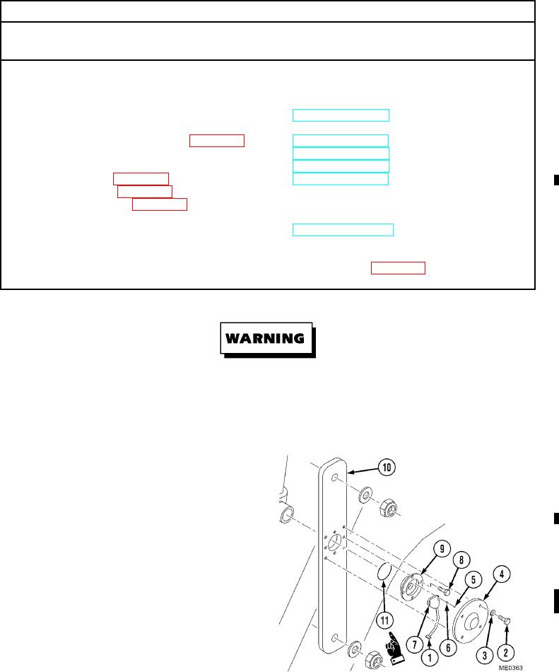
(1)
Disconnect potentiometer switch (1).
(2)
Remove four bolts (2), lockwashers (3), and
dust cover (4). Discard lockwashers.
(3)
Remove two screws (5), washers (6), and
potentiometer (7).
(4)
If required, remove four bolts (8) and
potentiometer plate (9) from FEL arm (10).
(5)
Remove O-ring (11) from potentiometer
plate (9). Discard O-ring.
Change 1