
TM 5-3805-294-23-4
0492
REMOVAL - Continued
18
15 16
17
19
20
21
14
HYEX01288
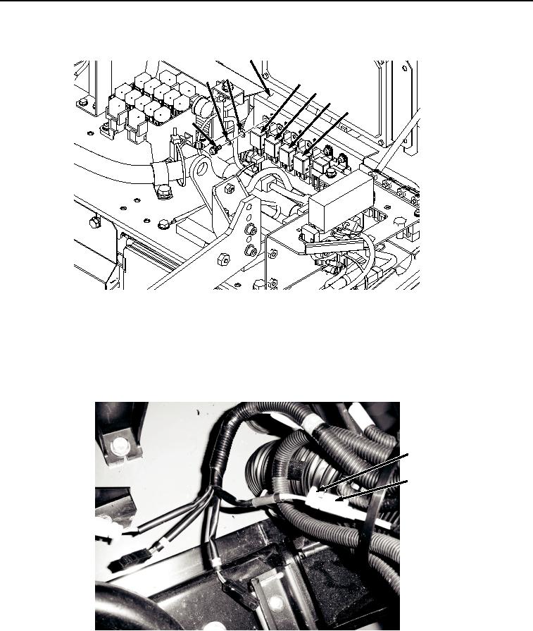
Figure 3. Auxiliary Control Wiring Harness (W15) Relays Removal.
7.
Repeat Step (6) to remove relays K31 (Figure 3, Item 19), K32 (Figure 3, Item 20), K33 (Figure 3, Item 21),
and hardware from bracket (Figure 3, Item 18).
8.
Disconnect auxiliary control wiring harness (W15) at connection S35 (Figure 4, Item 22) from left enable switch
connector S35 (Figure 4, Item 23).
22
23
HYEX01289
Figure 4.
Auxiliary Control Wiring Harness (W15) S35 Disconnect.
END OF TASK