
TM 5-3805-294-23-4
0492
INSTALLATION
WARNING
Ensure electrical power is off prior to working on all electrical connections. Prior to working
on or around vehicle, remove all jewelry, such as rings, ID tags, bracelets, etc. Jewelry, and
tools can catch on equipment, contact positive electrical circuits, and cause a direct short,
severe burns, or electrical shock. Failure to comply may result in injury or death to personnel.
NOTE
Install tie wraps as noted prior to removal.
1.
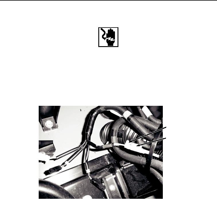
Connect left enable switch connector S35 (Figure 5, Item 23) to auxiliary control wiring harness (W15) at
connection S35 (Figure 5, Item 22).
22
23
HYEX01289
Figure 5. Auxiliary Control Wiring Harness (W15) S35 Connect.
2.
Install relay K33 (Figure 6, Item 21) to bracket (Figure 6, Item 18) with washer (Figure 6, Item 16), lockwasher
(Figure 6, Item 15), and screw (Figure 6, Item 14).