
TM 5-3805-294-23-4
0516
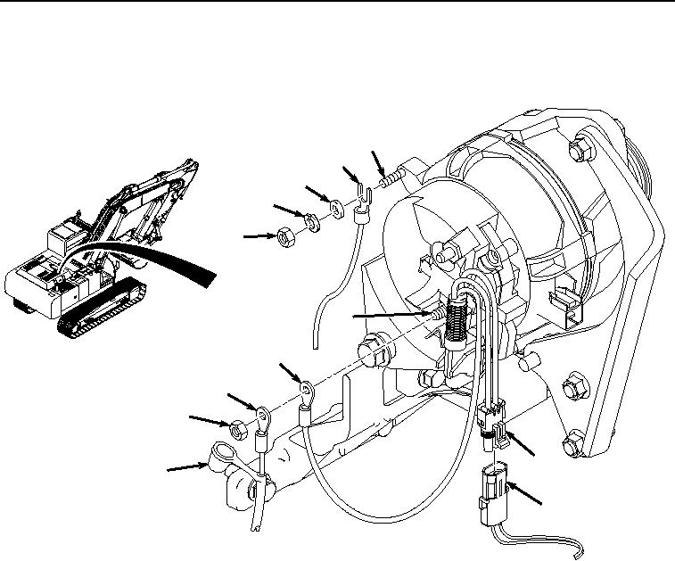
INSTALLATION - Continued
14.
Install ground wire connector (Figure 34, Item 151) to alternator ground stud (Figure 34, Item 152) with washer
(Figure 34, Item 150), lockwasher (Figure 34, Item 149), and nut (Figure 34, Item 148).
152
151
150
149
148
145
144
143
142
147
141
146
HYEX02498
Figure 34. Install Wiring Harness To Alternator.
15.
Connect wiring harness connector X70 (Figure 34, Item 146) to diode excite cable connector (Figure 34, Item
147).
16.
Install wiring harness power wire connector (Figure 34, Item 143) and alternator wiring harness connector
terminal (Figure 34, Item 144) to alternator positive stud (Figure 34, Item 145) with nut (Figure 34, Item 142).
17.
Install boot (Figure 34, Item 141) to alternator positive stud (Figure 34, Item 145) and nut (Figure 34, Item 142).
18.
Route cable along side of engine to starter motor and connect wiring harness connection X137 (Figure 35,
Item 139) to starter protection wiring harness connector X137 (Figure 35, Item 140).