
TM 5-3805-294-23-4
0516
INSTALLATION - Continued
140
135
134
14
139
133
137
14
136
138
8
8
HYEX02497
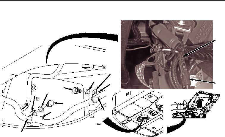
Figure 35.
Install Wiring Harness To Bracket X40 and Starter Protection Wiring Harness.
NOTE
Connector X40 separates machine harness W2 and pump wiring harness W8. At this point
W2 and W8 are considered machine wiring harness W2.
19.
Install connector (Figure 35, Item X40) (Figure 35, Item 138) and wiring harness (Figure 35, Item 8) to frame
(Figure 35, Item 14) with washer (Figure 35, Item 137) and bolt (Figure 35, Item 136).
20.
Install clamp (Figure 35, Item 135) and wiring harness (Figure 35, Item 8) to frame (Figure 35, Item 14) with
washer (Figure 35, Item 134) and bolt (Figure 35, Item 133).
21.
Install clamp (Figure 36, Item 132) and wiring harness (Figure 36, Item 8) to frame (Figure 36, Item 14) with
washer (Figure 36, Item 131) and bolt (Figure 36, Item 130).