
TM 5-3805-294-23-4
0516
INSTALLATION - Continued
40
8
40
30
27
31
40
33
26
32
35
29
43
37
28
39
40
42
41
38
34
36
14
HYEX02485
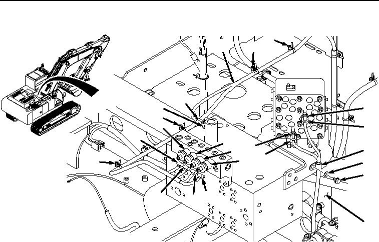
Figure 47. Install Wiring Harness To B33, B34, B31, Y23, Y22, Y25, and Y24.
58.
Install wiring harness (Figure 47, Item 8) to frame (Figure 47, Item 14) with four clips (Figure 47, Item 40).
59.
Connect wiring harness connector Y24 (Figure 47, Item 38) to power dig solenoid (Figure 47, Item 39).
60.
Connect wiring harness connector Y25 (Figure 47, Item 36) to travel speed solenoid (Figure 47, Item 37).
61.
Connect wiring harness connector Y22 (Figure 47, Item 34) to dig regenerative solenoid (Figure 47, Item 35).
62.
Connect wiring harness connector Y23 (Figure 47, Item 32) to arm regenerative solenoid (Figure 47, Item 33).
63.
Connect wiring harness connector B31 (Figure 47, Item 30) to arm in pressure sensor (Figure 47, Item 31).
64.
Connect wiring harness connector B34 (Figure 47, Item 28) to travel pressure sensor (Figure 47, Item 29).
65.
Connect wiring harness connector B33 (Figure 47, Item 26) to swing pressure sensor (Figure 47, Item 27).
66.
Connect wiring harness connector E2 (Figure 48, Item 24) to boom power wire harness (Figure 48, Item 25).