
TM 5-3805-294-23-4
0535
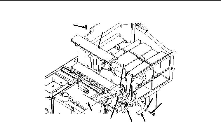
INSTALLATION - Continued
11
3
8
7
5
4
12
10
9
6
HYEX02014
Figure 5. Cover Removal.
4.
Lightly lubricate O-ring (Figure 5, Item 10) with clean refrigerant oil.
5.
Install O-ring (Figure 5, Item 10) to hose (Figure 5, Item 9).
6.
Install hose (Figure 5, Item 9) and O-ring (Figure 5, Item 10) to expansion valve (Figure 5, Item 8).
7.
Lightly lubricate O-ring (Figure 5, Item 7) with clean refrigerant oil.
8.
Install O-ring (Figure 5, Item 7) to hose (Figure 5, Item 6).
9.
Install hose (Figure 5, Item 6) and O-ring (Figure 5, Item 7) to expansion valve (Figure 5, Item 8) with screw
(Figure 5, Item 4) and washer (Figure 5, Item 5).