
TM 5-3805-294-23-4
0536
REMOVAL - Continued
16
19
22
15
14
3
21
20
12
13
18
17
10
HYEX02894
11
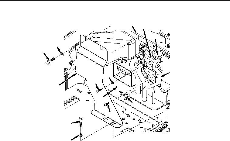
Figure 2.
Cover and Clamp Removal.
5.
Remove bolt (Figure 2, Item 14), washer (Figure 2, Item 15), and cover (Figure 2, Item 12) from bracket (Figure
2, Item 16) and floor (Figure 2, Item 13).
6.
Remove screw (Figure 2, Item 17) and clamp (Figure 2, Item 18) from hose (Figure 2, Item 3) and hose (Figure
2, Item 19).
7.
Remove bolt (Figure 2, Item 20) and washer (Figure 2, Item 21) from hose (Figure 2, Item 3) and evaporator
(Figure 2, Item 22).
8.
Remove hose (Figure 3, Item 3) and O-ring (Figure 3, Item 23) from evaporator (Figure 3, Item 22).