
TM 5-3805-294-23-4
0554
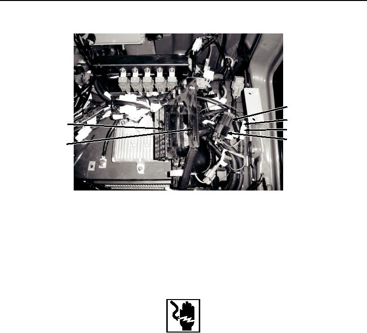
REMOVAL
31
33
35
34
32
26
HYEX01195
Figure 3. Auxiliary Fuse Box And Wiring Harness W13 Disconnect And Removal.
17.
Disconnect auxiliary fuse box wiring harness W13 connector X44 (Figure 3, Item 33) from cab wiring harness
W1 X44 (Figure 3, Item 34).
18.
Pull auxiliary fuse box wiring harness W13 (Figure 3, Item 35) through opening of bracket (Figure 3, Item 26).
END OF TASK
INSTALLATION
WARNING
Ensure electrical power is off prior to working on all electrical connections. Prior to working
on or around vehicle, remove all jewelry, such as rings, ID tags, bracelets, etc. Jewelry, and
tools can catch on equipment, contact positive electrical circuits, and cause a direct short,
severe burns, or electrical shock. Failure to comply may result in injury or death to personnel.
NOTE
Install tie wraps as required.
1.
Position auxiliary fuse box wiring harness W13 (Figure 4, Item 35) in front of bracket (Figure 4, Item 26).