
TM 5-3805-294-23-4
0554
INSTALLATION - Continued
4
3
2
1
5
6
7
8
10
22
9
12
11
16
15
13
17
17
22
18
19
20
14
21
HYEX01193
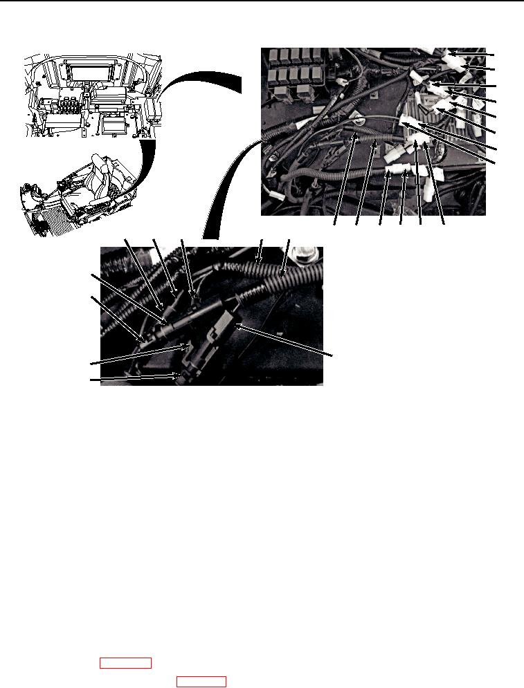
Figure 6. Auxiliary Fuse Box And Wiring Harness W13 Connect.
14.
Connect hydraulic hose reel and overload alarm wiring harnesses red wire (Figure 6, Item 12) to auxiliary fuse
box wiring harness W13 red wire connector AUX 3/X63 (Figure 6, Item 11).
15.
Connect deep dig pattern change wiring harness (Figure 6, Item 10) to auxiliary fuse box wiring harness W13
connector AUX 2/X62 (Figure 6, Item 9).
16.
Connect quick latch wiring harness (Figure 6, Item 8) to auxiliary fuse box wiring harness W13 connector
QUICK HITCH/X61 (Figure 6, Item 7).
17.
Connect cab rear work lights wiring harness (Figure 6, Item 6) to auxiliary fuse box wiring harness W13
connector CAB LAMP REAR/X57 (Figure 6, Item 5).
18.
Connect cab front work lights wiring harness (Figure 6, Item 4) to auxiliary fuse box wiring harness W13
connector CAB LAMP FRONT/X55 (Figure 6, Item 3).
19.
Connect heated air seat wiring harness W14 (Figure 6, Item 2) to auxiliary fuse box wiring harness W13
connector SEAT HEATER/X54 (Figure 6, Item 1).
END OF TASK
FOLLOW-ON MAINTENANCE
1.
Install rear tray. (WP 0566)
2.
Connect negative battery cable. (WP 0521)