
TM 5-3805-294-23-4
0555
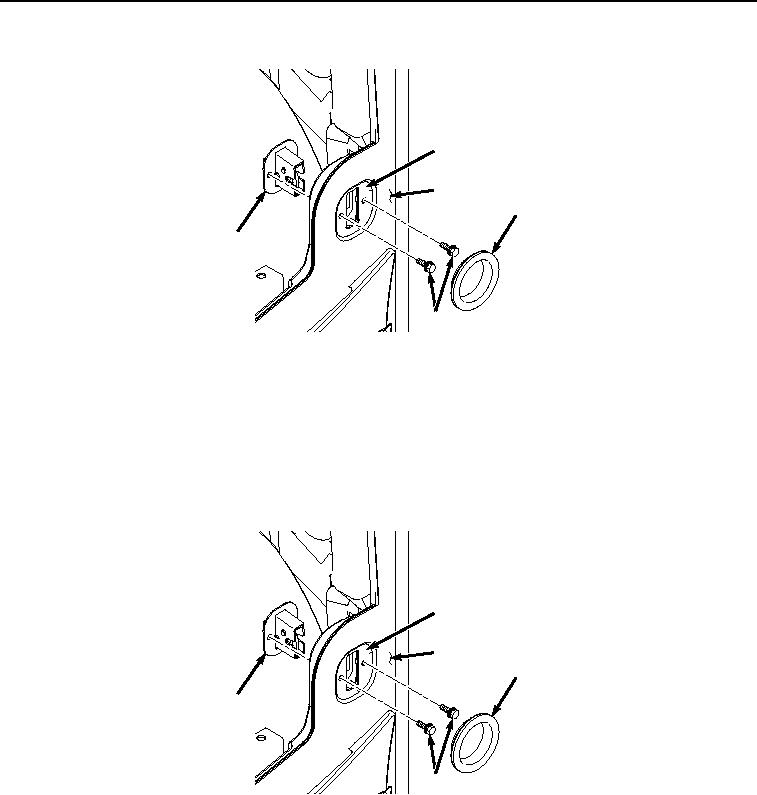
REMOVAL
3
19
18
21
20
HYEX03564
Figure 5. Latch Removal.
13.
Remove two bolts (Figure 5, Item 20) and latch (Figure 5, Item 21) from panel (Figure 5, Item 3).
END OF TASK
INSTALLATION
1.
Install latch (Figure 6, Item 21) to panel (Figure 6, Item 3) with two bolts (Figure 6, Item 20).
3
19
18
21
20
HYEX03564
Figure 6. Latch Installation.
2.
Install rubber grommet (Figure 6, Item 18) to glass (Figure 6, Item 19).
3.
Attach twine to cable (Figure 7, Item 9).