
TM 5-3805-294-23-4
0555
INSTALLATION - Continued
7
4
6
5
8
10
8
9
HYEX03563
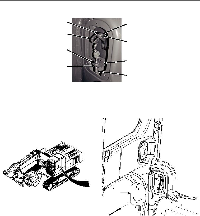
Figure 9.
Pin Removal.
11.
Install pin (Figure 9, Item 5) to bracket (Figure 9, Item 6) and latch (Figure 9, Item 7).
12.
Install retaining ring (Figure 9, Item 4) to pin (Figure 9, Item 5).
13.
Install cover (Figure 10, Item 2) to panel (Figure 10, Item 3) with three screws (Figure 10, Item 1).
2
3
1
HYEX01804
Figure 10. Latch Panel Cover Installation.
END OF TASK
ADJUSTMENT
1.
Remove three screws (Figure 11, Item 1) and cover (Figure 11, Item 2) from panel cover (Figure 11, Item 3).