
TM 5-3805-294-23-4
0555
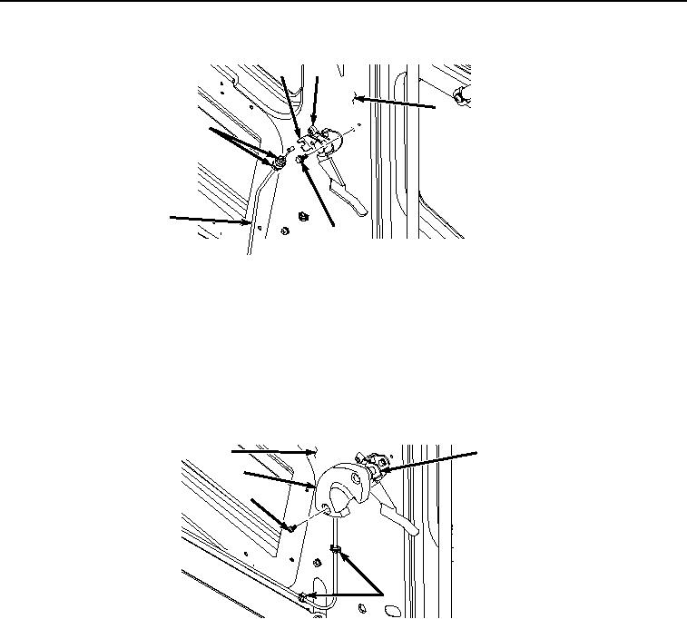
INSTALLATION - Continued
13
16
3
15
9
17
HYEX03565
Figure 7. Cable Installation.
4.
Pull cable (Figure 7, Item 9) and position on panel (Figure 7, Item 3).
5.
Remove twine from cable (Figure 7, Item 3).
6.
Install release handle (Figure 7, Item 13) to panel (Figure 7, Item 3) with two bolts (Figure 7, Item 17).
7.
Install cable (Figure 7, Item 9) to release handle (Figure 7, Item 13) and bracket (Figure 7, Item 16) with two
nuts (Figure 7, Item 15).
8.
Close two clips (Figure 8, Item 14).
3
13
12
11
14
HYEX03566
Figure 8. Lever Cover Removal.
9.
Install cover (Figure 8, Item 12) to release handle (Figure 8, Item 13) with two screws.
10.
Install cable (Figure 9, Item 9) to bracket (Figure 9, Item 10) with two nuts (Figure 9, Item 8).