
TM 5-3805-294-23-4
0554
REMOVAL - Continued
9.
Remove red wire splitter wiring harness (Figure 1, Item 17) from splitter wiring harnesses connector (Figure
1, Item 12). (WP 0511)
10.
Disconnect black wire splitter wiring harness connector (Figure 1, Item 18) from hydraulic hose reel wiring
harness connector (Figure 1, Item 19).
11.
Disconnect black wire splitter wiring harness connector (Figure 1, Item 20) from overload alarm wiring harness
connector (Figure 1, Item 21).
12.
Remove black wire splitter wiring harness (Figure 1, Item 22) from splitter wiring harnesses connector (Figure
1, Item 12). (WP 0511)
NOTE
Disassembly of the following brackets is necessary to access the remaining connections.
13.
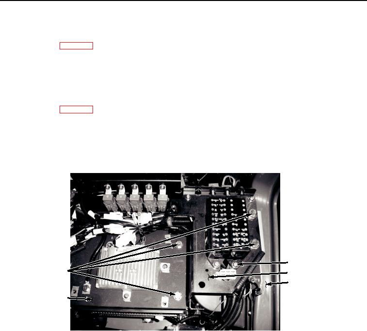
Remove two screws (Figure 2, Item 23), lockwashers (Figure 2, Item 24), and washers (Figure 2, Item 25) from
bracket (Figure 2, Item 26). Discard lockwashers.
23, 24, 25
27, 28
26
30
29
HYEX01194
Figure 2.
Bracket Disassembly.
NOTE
If HYEX is equipped with a Supplemental Armor Set, remove CCTV power supply from
bracket (26) using procedure found in TM 5-3805-295-13&P.
14.
Remove four bolts (Figure 2, Item 27) and washers (Figure 2, Item 28) from bracket (Figure 2, Item 26), bracket
(Figure 2, Item 29), and frame (Figure 2, Item 30).
15.
Turn bracket (Figure 2, Item 26) over to left and observe connections.
NOTE
Two connectors are attached from underneath bracket.
16.
Disconnect auxiliary fuse box wiring harness W13 connector X43 (Figure 3, Item 31) from cab wiring harness
W1 X43 (Figure 3, Item 32).