
TM 5-3805-294-23-4
0554
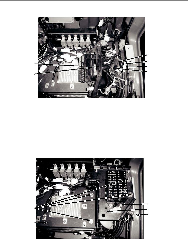
INSTALLATION - Continued
31
33
35
34
32
26
HYEX01195
Figure 4. Auxiliary Fuse Box and Wiring Harness W13 Installation.
2.
Pull auxiliary fuse box wiring harness W13 (Figure 4, Item 35) through opening of bracket (Figure 4, Item 26).
3.
Connect cab wiring harness W1 X44 (Figure 4, Item 34) to auxiliary fuse box wiring harness W13 connector
X44 (Figure 4, Item 33).
4.
Connect cab wiring harness W1 X43 (Figure 4, Item 32) to auxiliary fuse box wiring harness W13 connector
X43 (Figure 4, Item 31).
5.
Position auxiliary fuse box wiring harness W13 (Figure 4, Item 35) on bracket (Figure 4, Item 26).
6.
Install two washers (Figure 5, Item 25), lockwashers (Figure 5, Item 24), and screws (Figure 5, Item 23) to
bracket (Figure 5, Item 26).
23, 24, 25
27, 28
26
30
29
HYEX01194
Figure 5. Bracket Assembly.