
TM 5-3805-294-23-4
0577
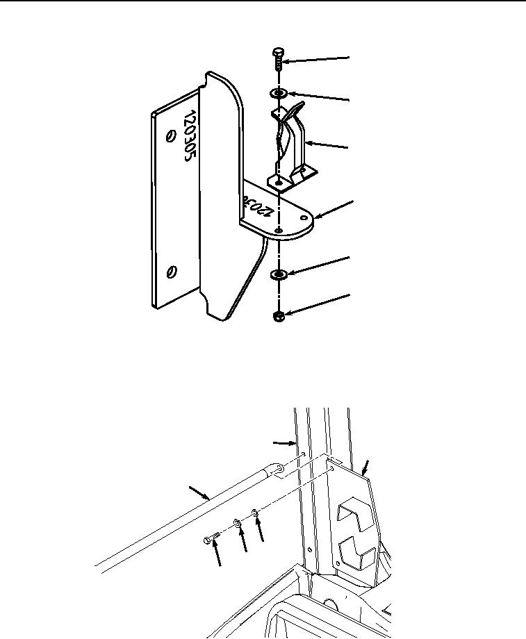
REMOVAL - Continued
7
8
10
3
8
9
HYEX01169
Figure 3. Rifle Clamp Removal.
4.
Remove two screws (Figure 4, Item 11), lockwashers (Figure 4, Item 12), washers (Figure 4, Item 13), rear
mount (Figure 4, Item 14), and guard bars (Figure 4, Item 5) from operator cab frame (Figure 4, Item 15).
Discard lockwashers.
15
14
5
13
12
11
HYEX01172
Figure 4.
Rifle Rear Mount Removal.