
TM 5-3805-294-23-4
0576
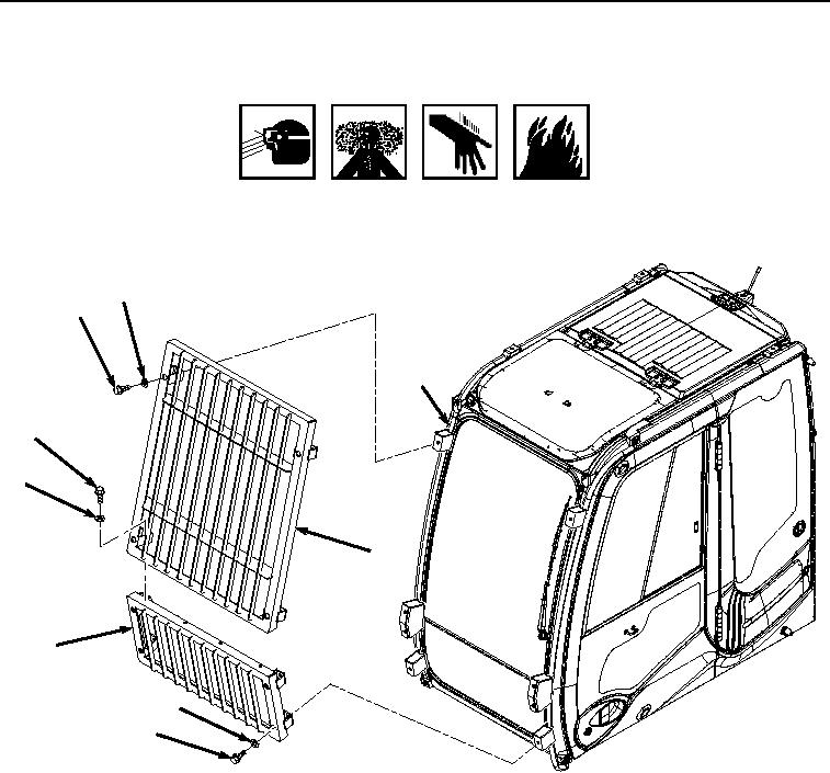
INSTALLATION
WARNING
ADHESIVES AND SEALANTS
1.
Apply thread lock to threads of four bolts (Figure 2, Item 8).
6
5
7
1
2
3
4
9
8
HYEX00239
Figure 2.
Operator Protection Guard Installation.
NOTE
Do not fully tighten the bolts (Figure 2, Item 5) and (Figure 2, Item 8) in Steps (2) and (4).
This will allow the lower protection guard (Figure 2, Item 4) and the upper protection guard
(Figure 2, Item 3) to be adjusted as necessary until all bolts are installed.
2.
With the aid of an assistant, install lower protection guard (Figure 2, Item 4) to operator cab frame (Figure 2,
Item 7) with four bolts (Figure 2, Item 8) and washers (Figure 2, Item 9). Do not fully tighten bolts (Figure 2,
Item 8) at this time.
3.
Apply thread lock to threads of four bolts (Figure 2, Item 5).