
TM 5-3805-294-23-4
0575
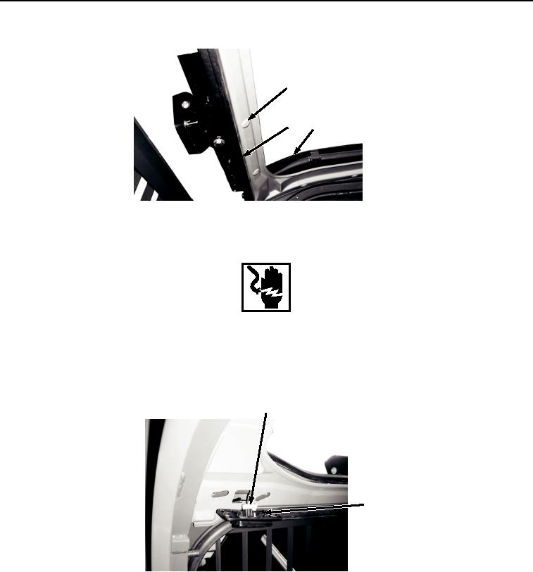
INSTALLATION - Continued
1
3
10
HYEX01654
Figure 8.
Headliner Front Cover Installation.
WARNING
Ensure electrical power is off prior to working on all electrical connections. Prior to working
on or around vehicle, remove all jewelry, such as rings, ID tags, bracelets, etc. Jewelry, and
tools can catch on equipment, contact positive electrical circuits, and cause a direct short,
severe burns, or electrical shock. Failure to comply may result in injury or death to personnel.
4.
Connect wire connector (Figure 9, Item 9) to electrical connector (Figure 9, Item 8).
9
8
HYEX01650
Figure 9.
Electrical Connector Wire Installation.
5.
Install electrical connector (Figure 10, Item 8) with two screws (Figure 10, Item 5), lockwashers (Figure 10,
Item 6), and washers (Figure 10, Item 7).