
TM 5-3805-294-23-4
0575
REMOVAL - Continued
1
3
10
HYEX01654
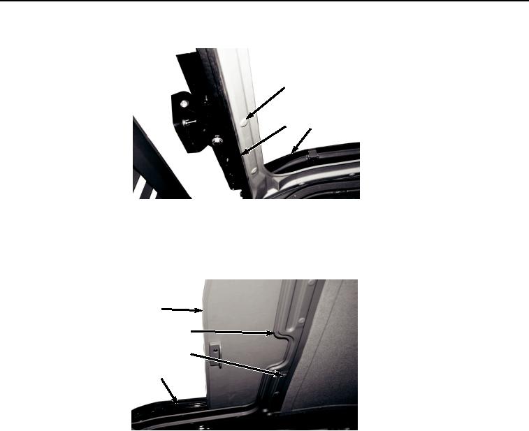
Figure 4.
Headliner Front Cover Removal.
6.
Remove front cover (Figure 4, Item 3) from cab (Figure 4, Item 10).
7.
Remove 14 clips (Figure 5, Item 1) from cover (Figure 5, Item 4).
11
4
1
10
HYEX01652
Figure 5.
Headliner Removal.
NOTE
Cover will need to be curled to remove at rear of cab.
8.
Remove cover (Figure 5, Item 4) from cab (Figure 5, Item 10).
9.
Remove 13 screws (Figure 6, Item 11) and washers (Figure 6, Item 12) from two rails (Figure 6, Item 13).