
TM 5-3805-294-23-4
0576
REMOVAL - Continued
6
5
7
1
2
3
4
9
8
HYEX00239
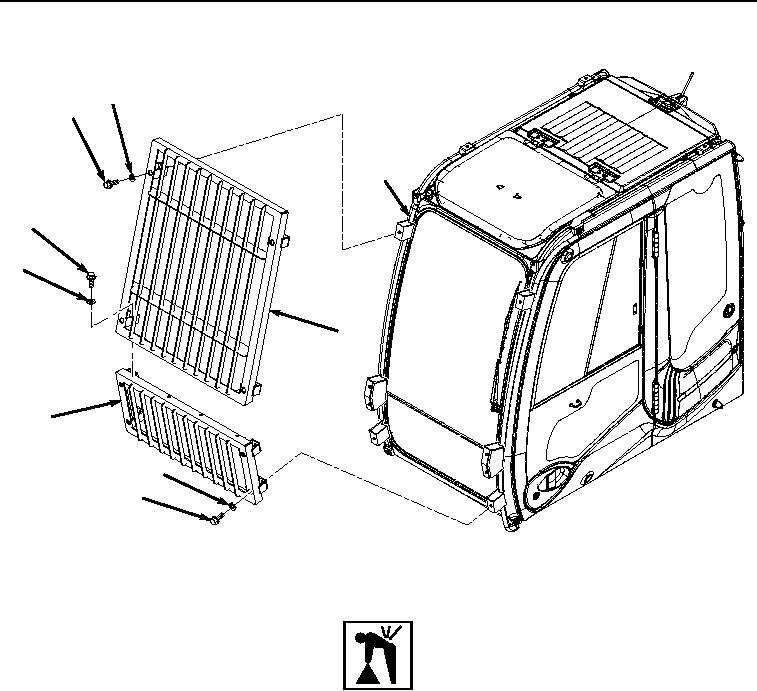
Figure 1. Operator Protection Guard Removal.
WARNING
Upper protection guard weighs approximately 78 lb (35.5 kg). Do not attempt to lift or move
upper protection guard without the aid of an assistant and a suitable lifting device. Failure to
comply may result in injury or death to personnel.
2.
With the aid of an assistant and a suitable lifting device, remove four bolts (Figure 1, Item 5), washers (Figure
1, Item 6), and upper protection guard (Figure 1, Item 3) from operator cab frame (Figure 1, Item 7).
3.
With the aid of an assistant, remove four bolts (Figure 1, Item 8), washers (Figure 1, Item 9), and lower
protection guard (Figure 1, Item 4) from operator cab frame (Figure 1, Item 7).
END OF TASK