
TM 5-3805-294-23-4
0577
REMOVAL
5.
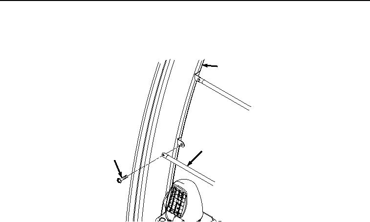
Remove two screws (Figure 5, Item 16) and guard bars (Figure 5, Item 5) from operator cab frame (Figure 5,
Item 15). Discard screws.
15
5
16
HYEX01173
Figure 5.
Guard Bar Removal.
END OF TASK
INSTALLATION
1.
Install two guard bars (Figure 6, Item 5) to operator cab frame (Figure 6, Item 15) with two screws (Figure 6,
Item 16).