
TM 5-3805-294-23-4
0577
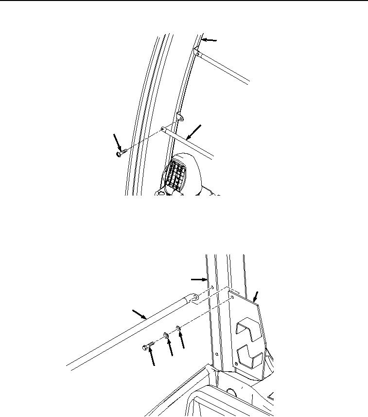
INSTALLATION - Continued
15
5
16
HYEX01173
Figure 6. Guard Bar Installation.
2.
Install two guard bars (Figure 7, Item 5) and rear mount (Figure 7, Item 14) to operator cab frame (Figure 7,
Item 15) with two screws (Figure 7, Item 11), lockwashers (Figure 7, Item 12), and washers (Figure 7, Item
13).
15
14
5
13
12
11
HYEX01172
Figure 7.
Rifle Rear Mount Installation.
3.
Install rifle clamp (Figure 8, Item 10) to clamp mount (Figure 8, Item 3) with two bolts (Figure 8, Item 7), four
washers (Figure 8, Item 8), and two locknuts (Figure 8, Item 9).