
TM 5-3805-294-23-4
0578
REMOVAL - Continued
6.
Disconnect harness W11 at connection X48 (Figure 2, Item 11) from air conditioner/heater controller (Figure
2, Item 12).
7.
Disconnect harness W11 at connection X49 (Figure 2, Item 13) from air conditioner/heater controller (Figure
2, Item 12).
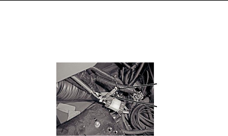
8.
Disconnect harness W11 at connection A (Figure 3, Item 14) from right control valve grip S7 at connection A
(Figure 3, Item 15).
14
15
HYEX01935
Figure 3.
Disconnect Harness From Right Control Valve Grip S7.
9.
Remove four screws (Figure 4, Item 16), lockwashers (Figure 4, Item 17), washers (Figure 4, Item 18), and
spacers (Figure 4, Item 19) from boot (Figure 4, Item 20) and cover (Figure 4, Item 21). Discard lockwashers.