• Home
  • Download PDF
  • Order CD-ROM
  • Order in Print
Figure 8. Left Bracket Installation.
Figure 10. Left Strap Installation.

Maintenance Manual For Hydraulic Excavator Type 1 With Hydraulic Thumb And Quick Latch -4 Page Navigation
  677    678    679    680    681  682  683    684    685    686    687  
img
.
TM 5-3805-294-23-4
0579
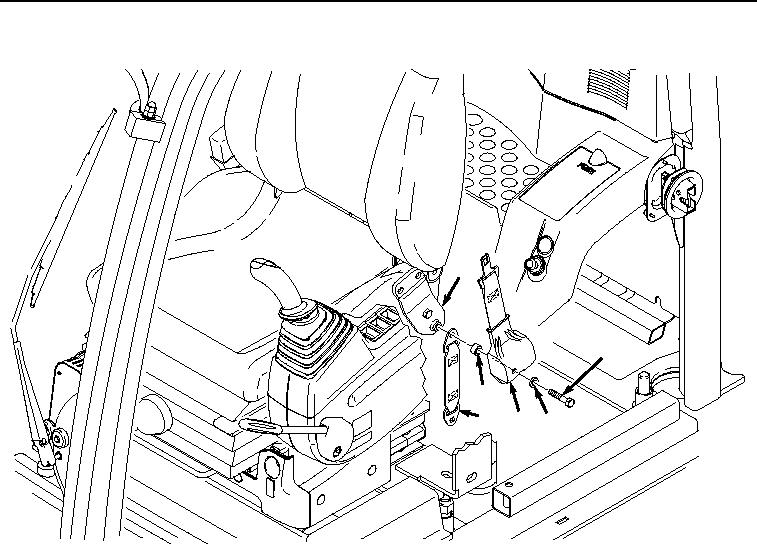
INSTALLATION - Continued
7
8
11
12
10
9
HYEX02333
Figure 9.
Left Belt Installation.
7.
Install two screws (Figure 10, Item 1), lockwashers (Figure 10, Item 2), washers (Figure 10, Item 3), washers
(Figure 10, Item 4), spacers (Figure 10, Item 5), and isolator (Figure 10, Item 6) to bracket (Figure 10, Item 7).
0579-10


Privacy Statement
Press Release
Contact

© Copyright Integrated Publishing, Inc.. All Rights Reserved.