
TM 5-3805-294-23-4
0579
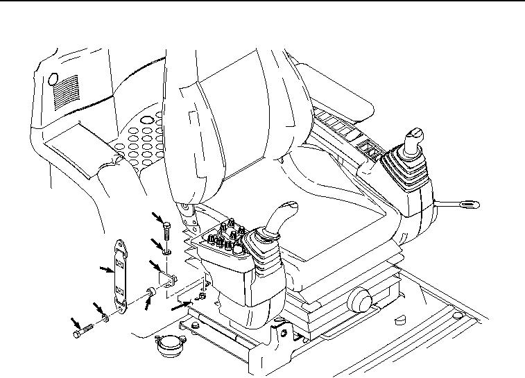
REMOVAL
31
32
30
24
28
29 19
27
HYEX02336
Figure 5. Right Bracket Removal.
8.
Remove bolt (Figure 5, Item 31), washer (Figure 5, Item 32), and bracket (Figure 5, Item 30) from seat stand
(Figure 5, Item 19).
END OF TASK
INSTALLATION
1.
Install bracket (Figure 6, Item 30) to seat stand (Figure 6, Item 19) with bolt (Figure 6, Item 31) and washer
(Figure 6, Item 32).