
TM 5-3805-294-23-4
0579
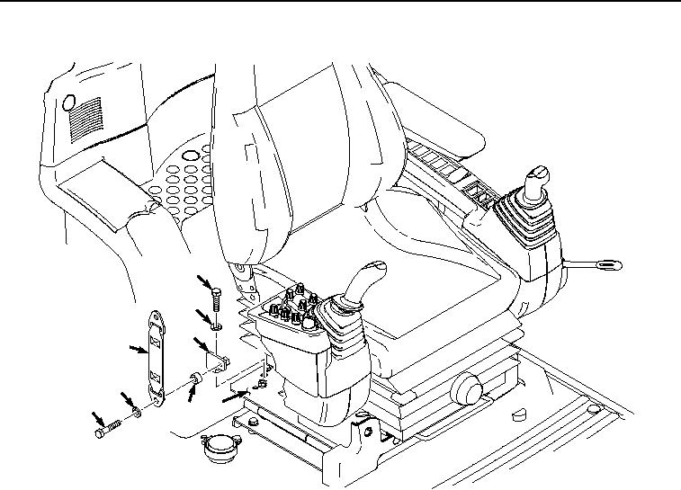
INSTALLATION - Continued
31
32
30
24
28
29 19
27
HYEX02336
Figure 6.
Right Bracket Installation.
2.
Install belt (Figure 6, Item 24) to bracket (Figure 6, Item 30) with bolt (Figure 6, Item 27), lockwasher (Figure
6, Item 28), and spacer (Figure 6, Item 29).
3.
Install belt (Figure 7, Item 24) and belt (Figure 7, Item 22) to seat (Figure 7, Item 26) with bolt (Figure 7, Item
20), lockwasher (Figure 7, Item 21), spacer (Figure 7, Item 23), and spacer (Figure 7, Item 25).