• Home
  • Download PDF
  • Order CD-ROM
  • Order in Print
Figure 6. Right Bracket Installation.
Figure 8. Left Bracket Installation.

Maintenance Manual For Hydraulic Excavator Type 1 With Hydraulic Thumb And Quick Latch -4 Page Navigation
  675    676    677    678    679  680  681    682    683    684    685  
img
.
TM 5-3805-294-23-4
0579
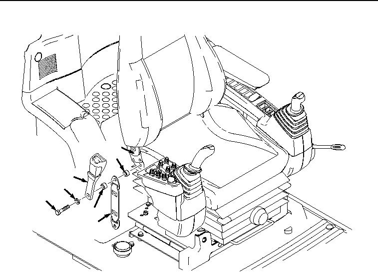
INSTALLATION - Continued
26
25
22
21
20
23
24
HYEX02335
Figure 7. Right Seat Belt Installation.
4.
Install bracket (Figure 8, Item 16) to seat stand (Figure 8, Item 19) with bolt (Figure 8, Item 17) and washer
(Figure 8, Item 18).
0579-8


Privacy Statement
Press Release
Contact

© Copyright Integrated Publishing, Inc.. All Rights Reserved.