
TM 5-3805-294-23-4
0579
INSTALLATION - Continued
17
18
12
16
14
13
19
15
HYEX02334
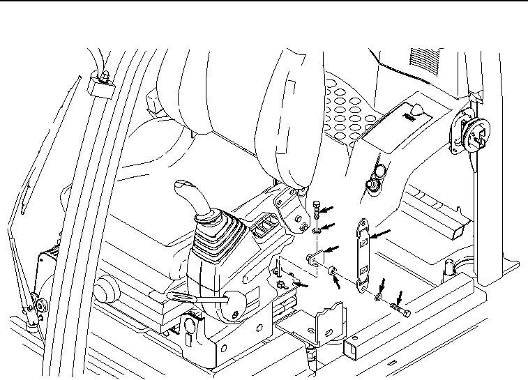
Figure 8.
Left Bracket Installation.
5.
Install belt (Figure 8, Item 12) to bracket (Figure 8, Item 16) with bolt (Figure 8, Item 13), lockwasher (Figure
8, Item 14), and spacer (Figure 8, Item 15).
6.
Install belt (Figure 9, Item 12) and belt (Figure 9, Item 10) to bracket (Figure 9, Item 7) with bolt (Figure 9, Item
8), lockwasher (Figure 9, Item 9), and spacer (Figure 9, Item 11).