
TM 5-3805-294-23-4
0579
REMOVAL - Continued
17
18
12
16
14
13
19
15
HYEX02334
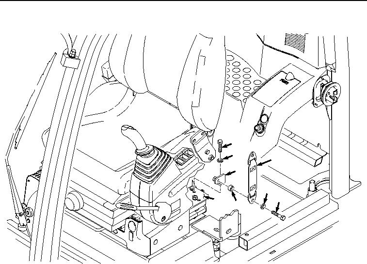
Figure 3.
Left Bracket Removal.
5.
Remove bolt (Figure 3, Item 17), washer (Figure 3, Item 18), and bracket (Figure 3, Item 16) from seat stand
(Figure 3, Item 19).
6.
Remove bolt (Figure 4, Item 20), lockwasher (Figure 4, Item 21), belt (Figure 4, Item 22), spacer (Figure 4,
Item 23), belt (Figure 4, Item 24), and spacer (Figure 4, Item 25) from seat (Figure 4, Item 26). Discard
lockwasher.