
TM 5-3805-294-23-4
0578
INSTALLATION - Continued
14
15
HYEX01935
Figure 10.
Connect Harness To Right Control Valve Grip S7.
15.
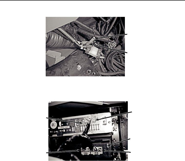
Connect harness W11 at connection X49 (Figure 11, Item 13) to air conditioner/heater controller (Figure 11,
Item 12).
9
10
12
11
13
HYEX01934
Figure 11. Connect Harness To Radio and AC/Heater Controller, A6, X48 and X49.
16.
Connect harness W11 at connection X48 (Figure 11, Item 11) to air conditioner/heater controller (Figure 11,
Item 12).
17.
Connect harness W11 at connection A6 (Figure 11, Item 9) to radio (Figure 11, Item 10).
18.
Connect harness W11 at connection X47 (Figure 12, Item 7) to cab wiring harness W1 at connection X47
(Figure 12, Item 8).