
TM 5-3805-294-23-4
0578
INSTALLATION - Continued
5
6
8
7
1
2
4
3
HYEX01933
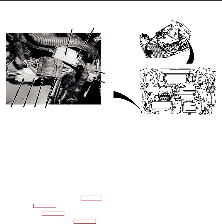
Figure 12. Connect Harness To Cab Wiring Harness X27, X38, X39, and X47.
19.
Connect harness W11 at connection X39 (Figure 12, Item 5) to cab wiring harness W1 at connection X39
(Figure 12, Item 6).
20.
Connect harness W11 at connection X38 (Figure 12, Item 3) to cab wiring harness W1 at connection X38
(Figure 12, Item 4).
21.
Connect cab wiring harness W1 at connection X27 (Figure 12, Item 1) to switch panel connector A9 (Figure
12, Item 2).
END OF TASK
FOLLOW-ON MAINTENANCE
1.
Install cab rear tray and rear cover. (WP 0566)
2.
Install seat. (WP 0580)
3.
Install seat belt. (WP 0579)
4.
Connect negative battery cable. (WP 0521)
5.
Perform the Standard Follow-On Maintenance Instructions. (Volume 3, WP 0384)
END OF TASK
END OF WORK PACKAGE