
TM 5-3805-294-23-4
0578
INSTALLATION - Continued
10.
Connect harness W11 connector B41 (Figure 8, Item 28) to air conditioner freeze control switch B41 (Figure
8, Item 29).
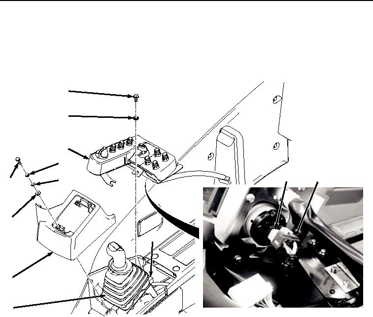
11.
Tilt right-hand switch console (Figure 9, Item 25) to left side and connect harness W11 at connection S1 (Figure
9, Item 26) to backside of key switch (Figure 9, Item 27).
23
24
25
17
27
26
18
16
19
22
21
20
HYEX01936
Figure 9.
Right-Hand Switch Console Installation To Connect S1.
12.
Install right-hand switch console (Figure 9, Item 25) to right-hand console (Figure 9, Item 22) with two washers
(Figure 9, Item 24), and two screws (Figure 9, Item 23).
13.
Install cover (Figure 9, Item 21) and boot (Figure 9, Item 20) to right-hand console (Figure 9, Item 22) with four
spacers (Figure 9, Item 19), washers (Figure 9, Item 18), lockwashers (Figure 9, Item 17), and screws (Figure
9, Item 16).
14.
Connect harness W11 at connection A (Figure 10, Item 14) to right control valve grip S7 at connection A (Figure
10, Item 15).