
TM 5-3805-294-23-4
0584
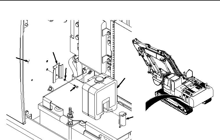
RESERVOIR AND PUMP REMOVAL - Continued
5
8
7
4
6
2
HYEX00635
Figure 2.
Reservoir and Pump Removal.
4.
Remove pump (Figure 2, Item 2) from reservoir (Figure 2, Item 4).
5.
Remove two screws (Figure 2, Item 6), washers (Figure 2, Item 7), and bracket (Figure 2, Item 5) from cover
(Figure 2, Item 8).
END OF TASK
SPRAY NOZZLE REMOVAL
1.
Remove screw (Figure 3, Item 9) and adapter fitting (Figure 3, Item 10) from cab (Figure 3, Item 11). Discard
screw.