
TM 5-3805-294-23-4
0584
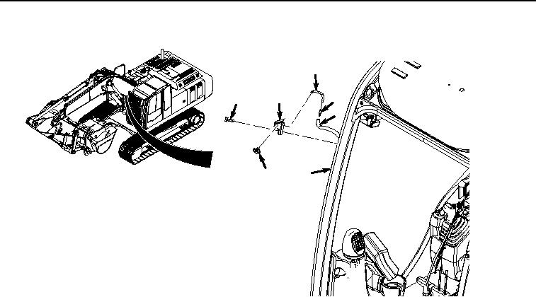
SPRAY NOZZLE INSTALLATION - Continued
13
10
12
9
3
14
11
HYEX00633
Figure 4.
Spray Nozzle Installation.
2.
Install hose (Figure 4, Item 13) to nozzle (Figure 4, Item 14).
3.
Install valve (Figure 4, Item 12) to hose (Figure 4, Item 13).
4.
Install hose (Figure 4, Item 3) to valve (Figure 4, Item 12).
5.
Install adapter fitting (Figure 4, Item 10) to cab (Figure 4, Item 11) with screw (Figure 4, Item 9).
END OF TASK
RESERVOIR AND PUMP INSTALLATION
1.
Install bracket (Figure 5, Item 5) to cover (Figure 5, Item 8) with two washers (Figure 5, Item 7) and screws
(Figure 5, Item 6).