
TM 5-3805-294-23-4
0626
ARM LINKS AND PINS REMOVAL - Continued
14.
Start engine (TM 5-3805-294-10). (Volume 5, WP 0794)
15.
With the aid of an assistant and suitable lifting device (Figure 7, Item 10), retract and raise bucket cylinder
(Figure 7, Item 11).
11
10
15
17 20
HYEX01122
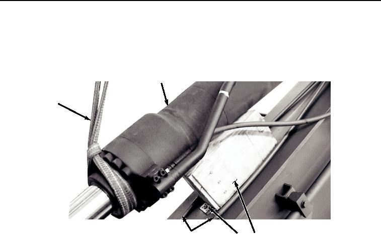
Figure 7.
Wood Block Installation.
16.
Position wood block (Figure 7, Item 20) between hoses (Figure 7, Item 15) and above arm (Figure 7, Item 17).
17.
With the aid of an assistant and suitable lifting device (Figure 7, Item 10), lower bucket cylinder (Figure 7, Item
11) to wood block (Figure 7, Item 20).
18.
Shut down engine (TM 5-3805-294-10). (Volume 5, WP 0794)
19.
Remove suitable lifting device (Figure 7, Item 10) from bucket cylinder (Figure 7, Item 11).
20.
Attach suitable lifting device (Figure 8, Item 10) to bucket link (Figure 8, Item 18).