
TM 5-3805-294-23-4
0626
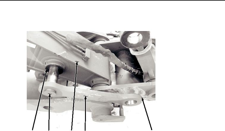
ARM LINKS AND PINS INSTALLATION - Continued
8.
Install shim (Figure 12, Item 22) to arm (Figure 12, Item 17).
22
7
17
19
21
HYEX01124
Figure 12.
Arm Link and Pin Installation.
9.
Apply grease to pin (Figure 12, Item 7).
10.
Install pin (Figure 12, Item 7) to arm link (Figure 12, Item 19).
11.
With the aid of an assistant, install arm link (Figure 12, Item 19) with pin (Figure 12, Item 7) to arm (Figure 12,
Item 17).
NOTE
It may be necessary to apply grease to shims for positioning.
Install shims equally on each side of component to get minimum amount of clearance in
joint.
12.
Install shim (Figure 12, Item 21) to arm link (Figure 12, Item 19).
13.
Apply grease to pin (Figure 13, Item 4).