
TM 5-3805-294-23-4
0626
ARM LINKS AND PINS INSTALLATION - Continued
17.
With the aid of an assistant and suitable lifting device (Figure 14, Item 10), raise bucket cylinder (Figure 14,
Item 11) from wood block (Figure 14, Item 20).
18.
Remove wood block (Figure 14, Item 20) between hoses (Figure 14, Item 15) and above arm (Figure 14, Item
17).
19.
Start engine (TM 5-3805-294-10). (Volume 5, WP 0794)
CAUTION
Slowly extend cylinder to align pin bores so shims are not damaged as pin is installed. Failure
to comply may result in damage to equipment.
20.
With the aid of an assistant and suitable lifting device (Figure 14, Item 10), extend and lower bucket cylinder
(Figure 14, Item 11) until pin holes are aligned.
21.
Shut down engine (TM 5-3805-294-10). (Volume 5, WP 0794)
22.
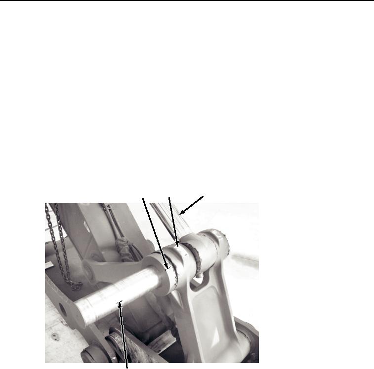
Install pin (Figure 15, Item 4) to bucket cylinder (Figure 15, Item 11), left side of bucket link (Figure 15, Item
18), and arm link (Figure 15, Item 19).
19
18
11
4
HYEX01121
Figure 15. Bucket Cylinder Rod End Installation.
23.
Install hose retainer (Figure 16, Item 16) to arm (Figure 16, Item 17).