
TM 5-3805-294-23-4
0626
ARM LINKS AND PINS INSTALLATION - Continued
29.
Install shim (Figure 19, Item 8) to pin (Figure 19, Item 4).
30.
Install arm link (Figure 19, Item 3) to pin (Figure 19, Item 4) and pin (Figure 19, Item 7).
31.
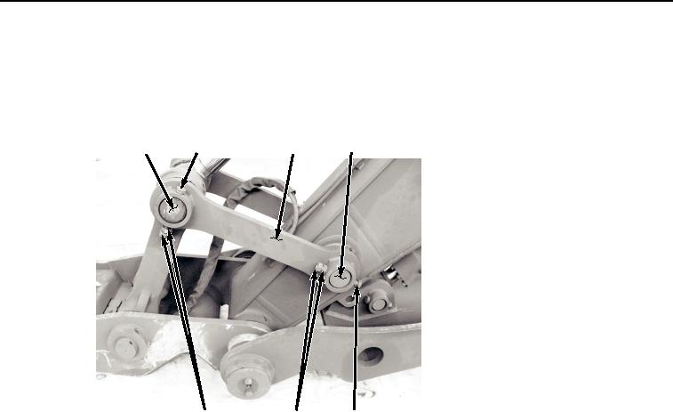
Install bolt (Figure 20, Item 6) to arm link (Figure 20, Item 3) and pin (Figure 20, Item 7).
4
2
3
7
1
5
6
HYEX01116
Figure 20. Arm Link and Bolt Installation.
32.
Install two nuts (Figure 20, Item 5) to bolt (Figure 20, Item 6).
NOTE
Tighten nuts (Figure 20, Item 5) against each other. Bolt (Figure 20, Item 6) must be free to
spin in hole.
33.
Tighten two nuts (Figure 20, Item 5) against each other to 400 lb-ft (540 Nm).
34.
Install bolt (Figure 20, Item 2) to arm link (Figure 20, Item 3) and pin (Figure 20, Item 4).
35.
Install two nuts (Figure 20, Item 1) to bolt (Figure 20, Item 2).
NOTE
Tighten nuts (Figure 20, Item 1) against each other. Bolt (Figure 20, Item 2) must be free to
spin in hole.
36.
Tighten two nuts (Figure 20, Item 1) against each other to 400 lb-ft (540 Nm).
END OF TASK
FOLLOW-ON MAINTENANCE
1.
Lubricate all pivot points (TM 5-3805-294-10). (Volume 5, WP 0794)