
TM 5-3805-294-23-4
0628
REMOVAL - Continued
CAUTION
Wipe area clean around all fluid connections prior to removal. Cap and plug all hoses, lines,
fittings, and ports during removal to prevent contamination of system components. Systems
must be kept clean from contaminants. Failure to comply may result in damage to equipment.
NOTE
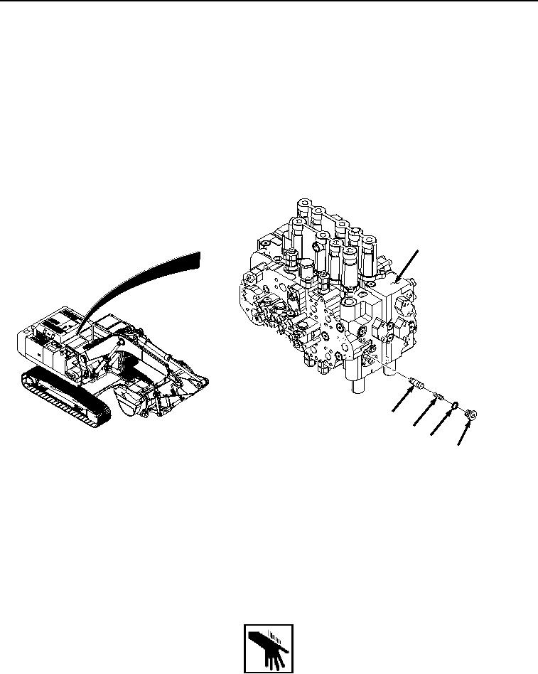
Check valve is on the front of the control valve.
Position drain pan under component being removed.
1.
Remove plug (Figure 1, Item 1) and O-ring (Figure 1, Item 2) from control valve (Figure 1, Item 3).
3
5
4
2
1
HYEX03371
Figure 1.
Check Valve Removal.
2.
Remove O-ring (Figure 1, Item 2) from plug (Figure 1, Item 1). Discard O-ring.
3.
Remove spring (Figure 1, Item 4) from control valve (Figure 1, Item 3).
4.
Remove poppet (Figure 1, Item 5) from control valve (Figure 1, Item 3).
END OF TASK
INSTALLATION
WARNING
1.
Lightly lubricate poppet (Figure 2, Item 5) with clean oil.