
TM 5-3805-294-23-4
0629
ARM REMOVAL - Continued
9
10
8
5
HYEX02267
7
4
6
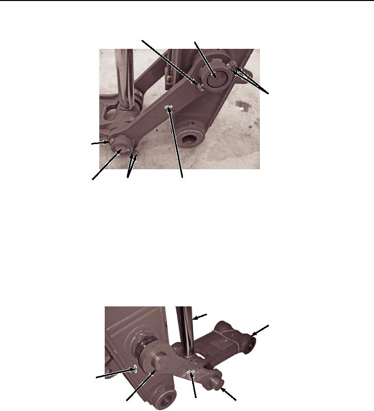
Figure 3. Arm Link Removal.
8.
Remove two nuts (Figure 3, Item 8) and bolt (Figure 3, Item 9) from arm link (Figure 3, Item 6) and pin (Figure
3, Item 10).
9.
Remove arm link (Figure 3, Item 6) from pin (Figure 3, Item 7) and pin (Figure 3, Item 10).
NOTE
Note position and amount of shims during removal to ensure proper installation.
10.
Remove pin (Figure 4, Item 7) and two shims (Figure 4, Item 11) from bucket link (Figure 4, Item 2), bucket
cylinder (Figure 4, Item 3), and arm link (Figure 4, Item 12).
3
2
14
10, 13
7, 11
12
HYEX02268
Figure 4.
Arm Link Pins Removal.
11.
Remove pin (Figure 4, Item 10), two shims (Figure 4, Item 13), and arm link (Figure 4, Item 12) from arm (Figure
4, Item 14).
12.
Remove three bolts (Figure 5, Item 15), plates (Figure 5, Item 16), and retainers (Figure 5, Item 17) from hose
(Figure 5, Item 18) and hose (Figure 5, Item 19).