
TM 5-3805-294-23-4
0629
ARM REMOVAL - Continued
residual pressure to relieve before continuing to open lines and hoses. Failure to comply may
result in injury or death to personnel.
CAUTION
Wipe area clean around all fluid connections prior to removal. Cap and plug all hoses, lines,
fittings, and ports during removal to prevent contamination of system components. Systems
must be kept clean from contaminants. Failure to comply may result in damage to equipment.
NOTE
Position drain pan under hoses being removed.
Tag and mark hoses during removal to ensure proper installation.
31.
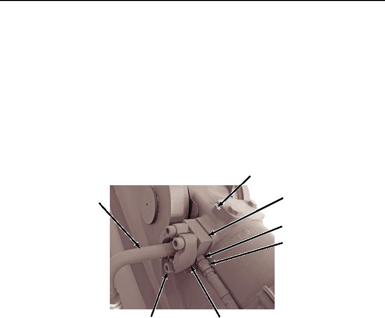
Remove hose (Figure 10, Item 29) from fitting (Figure 10, Item 30).
3
35, 36
33, 34
30
29
31
32
HYEX02272
Figure 10. Right Bucket Cylinder Hose Removal.
32.
Remove four screws (Figure 10, Item 31), two clamps (Figure 10, Item 32), hose (Figure 10, Item 33), O-ring
(Figure 10, Item 34), plate (Figure 10, Item 35), and O-ring (Figure 10, Item 36) from bucket cylinder (Figure
10, Item 3).
33.
Remove O-ring (Figure 10, Item 34) from hose (Figure 10, Item 33). Discard O-ring.
34.
Remove O-ring (Figure 10, Item 36) from plate (Figure 10, Item 35). Discard O-ring.
35.
Remove hose (Figure 11, Item 37) and O-ring (Figure 11, Item 38) from fitting (Figure 11, Item 39). Discard
O-ring.