
TM 5-3805-294-23-4
0629
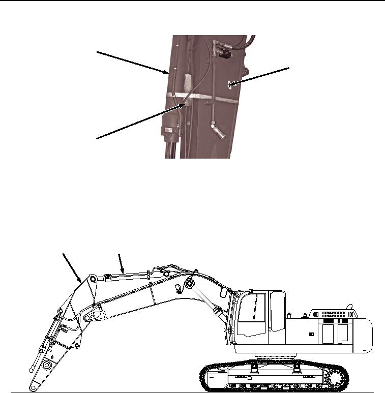
ARM REMOVAL - Continued
3
14
21
HYEX02271
Figure 7.
Wood Block Installation.
16.
Secure bucket cylinder (Figure 7, Item 3) to arm (Figure 7, Item 14).
17.
Start engine (TM 5-3805-294-10).
18.
Reposition arm (Figure 8, Item 14) leaving approximately 6 in. (15 cm) of travel on arm cylinder (Figure 8, Item
21).
14
21
HYEX03553
Figure 8.
Reposition Arm.
19.
Shut engine off (TM 5-3805-294-10).
20.
Remove two nuts (Figure 9, Item 22) and screw (Figure 9, Item 23) from arm cylinder pin (Figure 9, Item 24)
and arm (Figure 9, Item 14).